Calculation formulas
HCM 6th Edition basic freeway method, with SAF = CAF = 1. Keep full precision until displaying results.
1. Free-flow speed (Eq. 12-2)
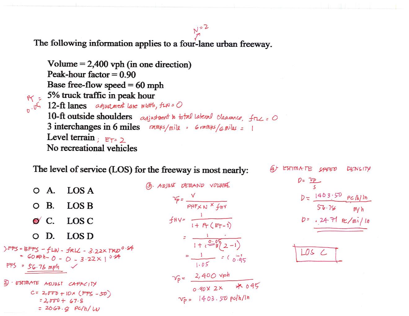
FFS = BFFS − fLW − fRLC − 3.22 × TRD0.84
BFFS is base free-flow speed; TRD is ramps per mile. Use measured FFS directly when available.
Lane penalty fLW = 0 at widths ≥12 ft, 1.9 mph for 11–<12 ft, and 6.6 mph for 10–<11 ft (Exhibit 12-20).
fRLC = [6 − min(clearance, 6)] × k
Exhibit 12-21 is linear between clearance rows: k = 0.6, 0.4, 0.2, or 0.1 mph/ft for 2, 3, 4, or ≥5 directional lanes, respectively.
2. Heavy vehicles and flow (Eqs. 12-9, 12-10)
fHV = 1 / [1 + PT(ET − 1)]
vp = V / (PHF × N × fHV)
PT is the heavy-vehicle percentage divided by 100; ET is its passenger-car equivalent (2 for level terrain, 3 for rolling terrain, or a specific-grade lookup). V is directional demand in veh/h; N is directional lanes; vp is passenger-car flow in pc/h/ln.
3. Capacity, speed, density (Eq. 12-6, Eq. 12-1, Exhibit 12-6)
c = min[2,200 + 10(FFS − 50), 2,400]
BP = 1,000 + 40(75 − FFS)
Capacity c and speed-curve breakpoint BP are in pc/h/ln. The supported FFS range is 55–75 mph.
S = FFS, when vp ≤ BP
S = FFS − (FFS − c/45) × [(vp − BP)/(c − BP)]2, when BP < vp ≤ c
D = vp / S
S is average speed in mph; D is density in pc/mi/ln. Demand above capacity is LOS F; the basic segment method does not predict speed or density in that condition.
| LOS | Density (pc/mi/ln) |
|---|---|
| A | 0–11 |
| B | >11–18 |
| C | >18–26 |
| D | >26–35 |
| E | >35–45 |
| F | Demand exceeds capacity, or density >45 |
Sources and edition
Supplied HCM Chapter 12 extract (Version 6.0, pp. 12-17–12-39) and the previously reviewed 6th Edition Exhibit 12-6 (p. 12-10). Specific-grade PCEs reuse the multilane calculator's verified Chapter 12 tables.
Audit and source reconciliation records corrections to the archived Python script and worked example. The example's LOS remains C with corrected arithmetic.
The supplied HCM 7th Edition reference guide is available for review. This calculator implements the verified 6th Edition base method; it does not implement the 7th Edition's connected/automated-vehicle adjustments.